Using Vivado 2018.3 .
Block Diagram
Changes to Microblaze1 Hello World LED | QY’s Notes:
- An AXI Interrrupt Controller
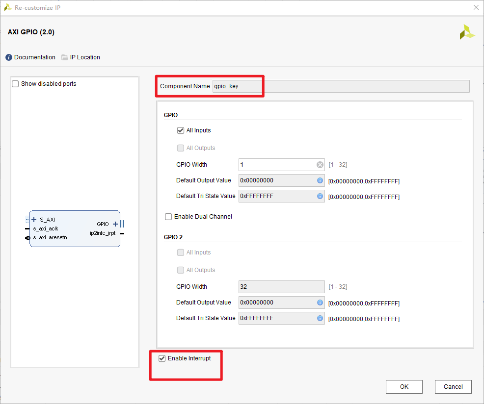
- Another AXI_GPIO IP,
gpio_key- enable GPIO interrupt
- the interrupt output is connected to AXI Interrrupt Controller
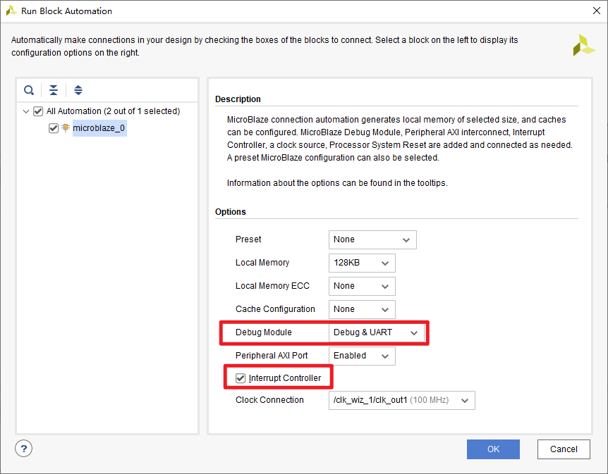
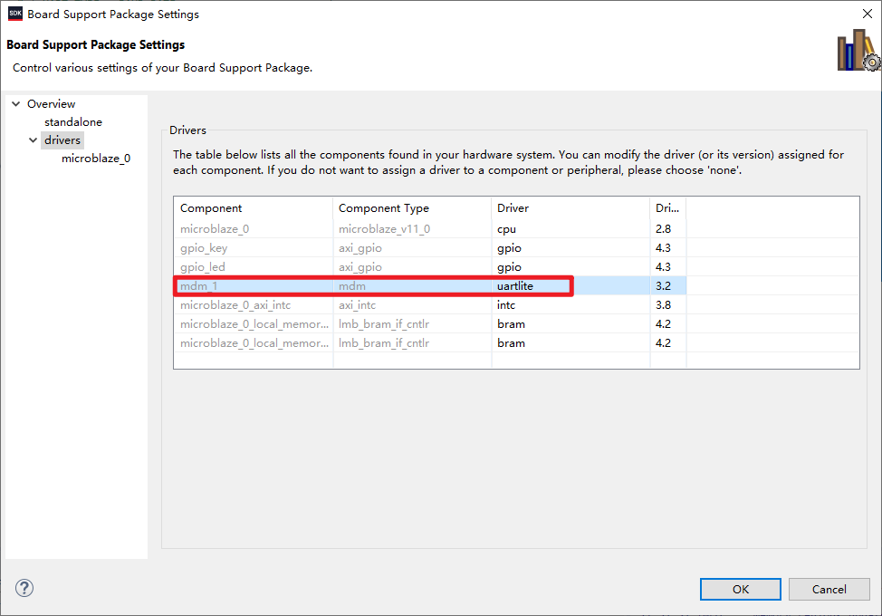
- MDM module, enable
JTAG UART
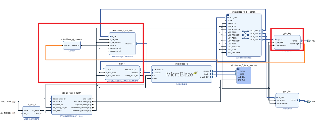
Microblaze
- Enable
interrupt controller - Increase Local Memory to
128 KB
Key GPIO
Enable interrupt
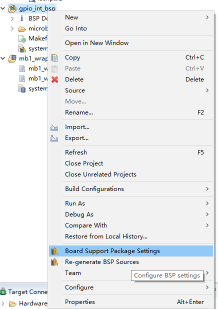
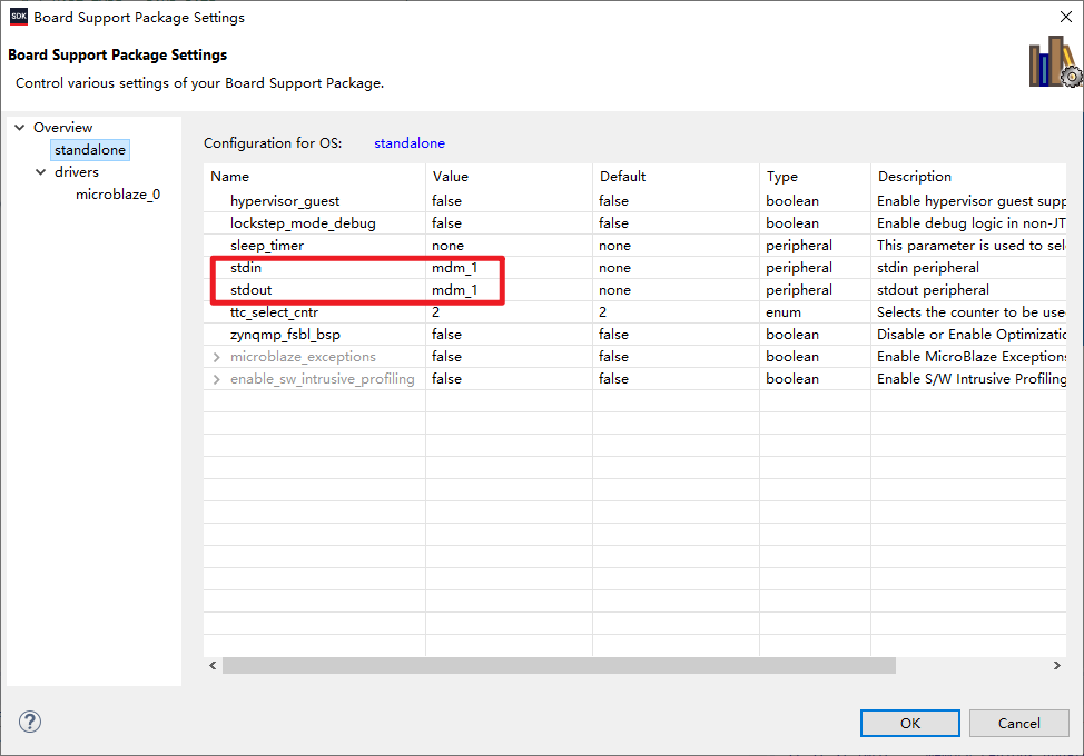
SDK
BSP Settings
Settings to direct print()/xil_printf() output to JTAG UART (nomarlly, these are the default, since only one UART is present here).
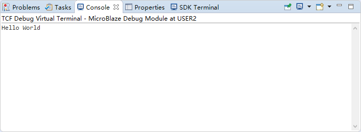
Sample Code
Just a helloworld…
| |
Debug
The output is printed in the Console.
JTAG UART could be useful for debugging. However, sending stuff to it seems compicated.
For example, in this link: MicroBlaze bare metal JTAG UART how do I receive/input/stdin? (xilinx.com)
I am trying to number these posts based on the hardware platform, i.e., the block diagram in Vivado. So the y-th application from the x-th block diagram would be x.y.
My end goal here is just to control an iic device with MicroBlaze, but I will firstly work on modules such as interrupt, timer and uart, because I find the AXI_IIC IP and the APIs a bit confusing and seem to require some other IPs such as the interrupt.