Using Vivado 2018.3 .
Introduction
In this post, the previous blinking LED project, Microblaze1 Hello World LED, is programmed into a flash.
When the code size is small enough to fit in the BRAM, then, the flash configuration is easier and requires no bootloader or external RAM. We only need to include the application program (in this case, the blinking LED program) in the microblaze bitstream and store the bitstream in the flash.
- 4-wire SPI configuration
- Associate the
.elffile in theupdatedbitstream - Generate mcs file
- Program SPI Flash
- Boot from SPI Flash
Generate bitstream
4-wire SPI constraints
Add to .xdc file (Of cources, the board and flash shoud support 4-wire SPI mode, and the correct voltage level should be used.):
#############SPI Configurate Setting###################
#4-wire SPI
set_property CFGBVS VCCO [current_design]
set_property CONFIG_VOLTAGE 3.3 [current_design]
set_property BITSTREAM.CONFIG.SPI_BUSWIDTH 4 [current_design]
set_property CONFIG_MODE SPIx4 [current_design]
set_property BITSTREAM.CONFIG.CONFIGRATE 50 [current_design]
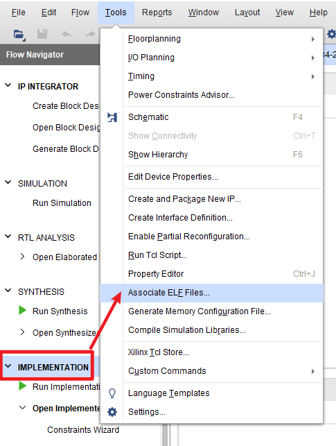
Associate ELF Files
In Synthesis/Implementation, select: Tools-Associate ELF Files.
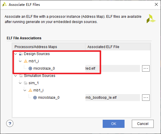
Select the correct elf file: (The build output of our application project (led.elf),not the default mb_bootloop_le.elf)
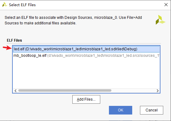
Click OK, and re-run sythesis-implementation-generate bitstream.
Generate mcs File
Tools-Generate Memory Configuration Files.
- Select the corrent memory part. On my board,
MT25QL128, (alias N25Q128). - Enter a file name,
test_led.mcs - Select SPIx4
- Select
Write checksumandOverwrite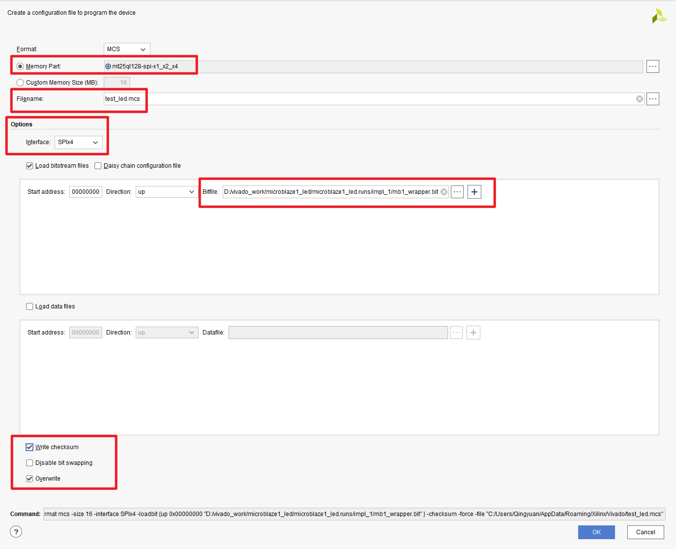
Program QSPI Flash
From the left panel, open Hardware manager, then auto-connect to the board.
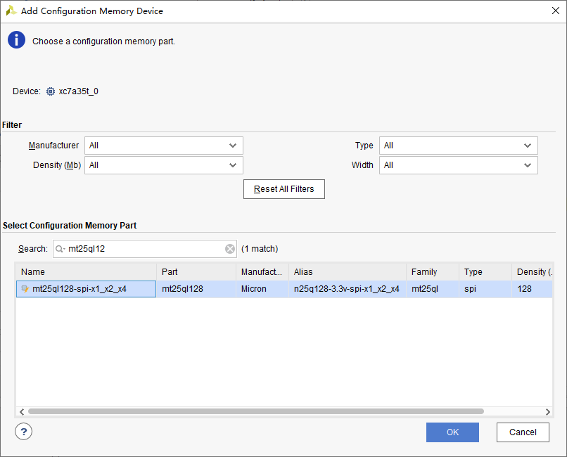
Add Configuration Memory Device
Right click the device-Add Configuration Memory Device. Again, mt25ql128, (alias N25Q128)
Right click the memory device-Program-select the generated test_led.mcs.
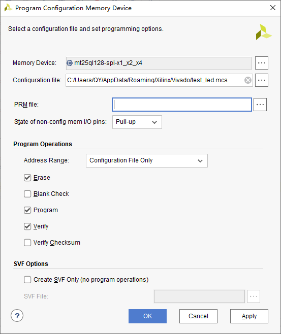
After programming Flash, select the FPGA device, right click-Boot from Configuration Memory Device, the LED should start blinking (when using 4-wire SPI, it takes less than 1 second to load the bitstream).
If the bitstream does not load after power-up (but loads after pressing PROGRAM_B button ), remove the JTAG cable and try again:
- Artix-7 Power-Up configuration is not done (xilinx.com)
- 66954 - 2016.1 and newer Vivado Hardware Manager - Intermittent configuration failures can occur when the FPGA is power cycled and the programming cable is connected. (xilinx.com)
Resource
No Bootloader Version
BIN and MCS Files
Still a bit confused.
- What is the exact image of what needs to go on the FLASH memory. (bin, bit, mcs, …. ?) (xilinx.com)
- MCS Vs BIN file (xilinx.com)
jimbrady (Customer): The MCS file is a HEX file where two ASCII chars are used to represent each byte of data. And the binary file of course just contains just the raw byte stream, in sequence. So the MCS file seems less efficient, because it takes 2 bytes to represent 1 byte. But it has a couple of advantages (1) It has a checksum at the end of each line for integrity. (2) Each line includes the address where the line should be located in memory. So for example, if a MCS file contains a few segments located far apart in address space, it can be small while the equivalent binary file might be huge, because it would have a lot of 0x00 or 0xFFs to fill the space between segments.