1 Introduction
This post is a step-by-step guide implementing a blinking LED project with MicroBlaze:
- Create a minimal MicroBlaze project
- Sample code for blinking LED (based on a Xilinx demo)
- Implementation on the demo board
I am new to FPGA and MicroBlaze, and I learned these all from the tutorials I found. References are at the end.
I used:
- Device: xc7a35tfgg484-2, (an Artix-7 Mini board made by a Chinese company, Wildfire)
- Vivado 2018.3
2 In Vivado
New RTL project and select the correct device.
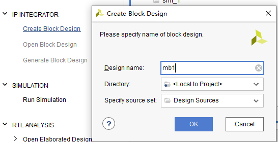
2.1 New Block Design
IP integrator-Create Block Design.
2.2 Add MicroBlaze IP
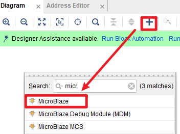
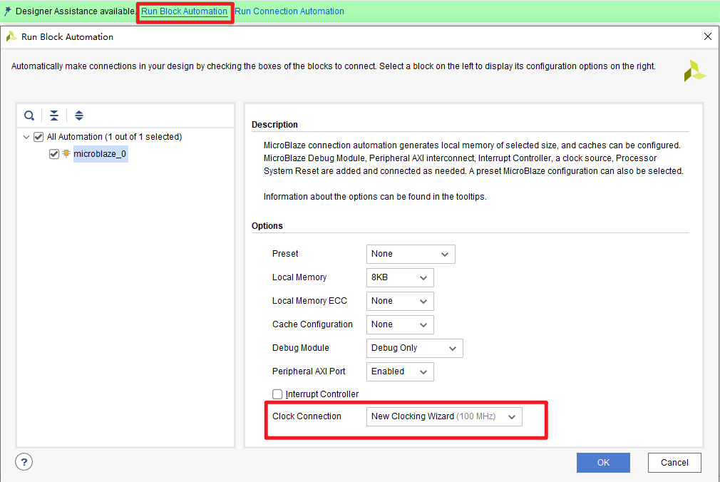
Run Block Automation:
- Choose
New Clocking Wizard, because the board has a 50 MHz input clock, and the microblaze core seems to need a 100 MHz clock. - Other setting default.
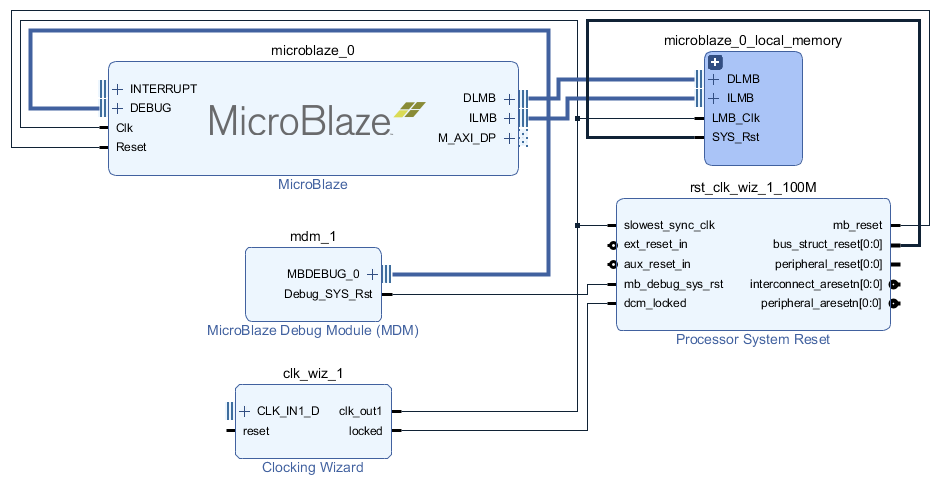
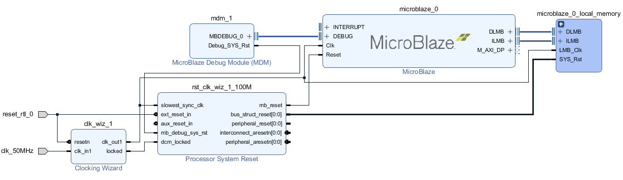
After block automation, a few other IPs are added and connected:
2.3 Clocking wizard
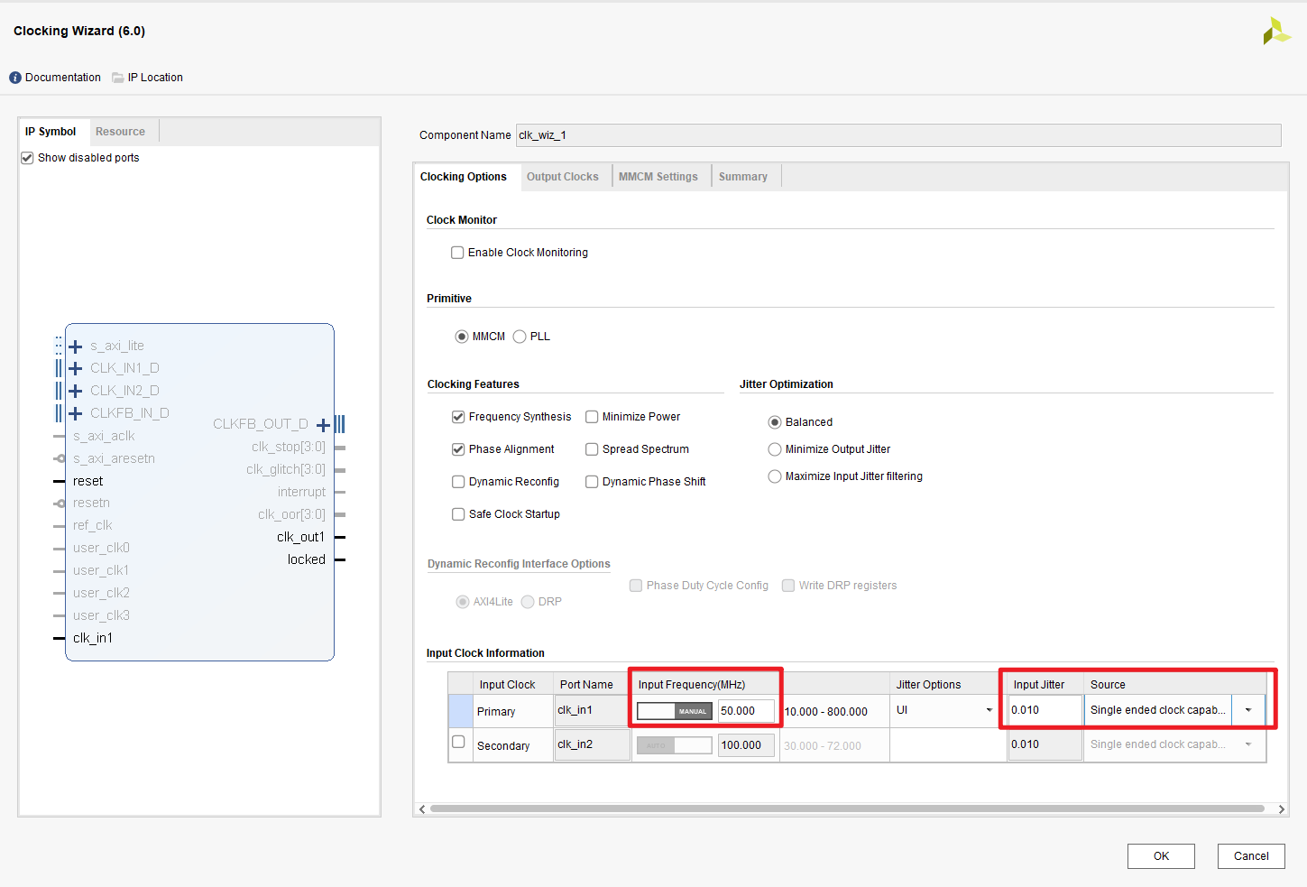
Input Clock-Source-single ended clock capable, also, correct frequency,50 MHz.Output Clocks-Reset Type-select Active Low, to matching the schematics below (KEY1is Low when the button is pushed):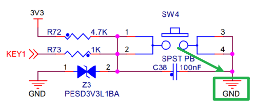
2.4 Connection Automation
Run Connection Automation:
 (I don’t know how this button can be accessed from the menu…)
Input ports for reset and clock are added automatically:
- The generated port name was
clk_100MHZ, I changed it toclk_50MHZ, to avoid confusion - Two reset ports were generated, and I merged them into one.
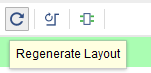
Regenerate Layout: useful button to organize the schematics.
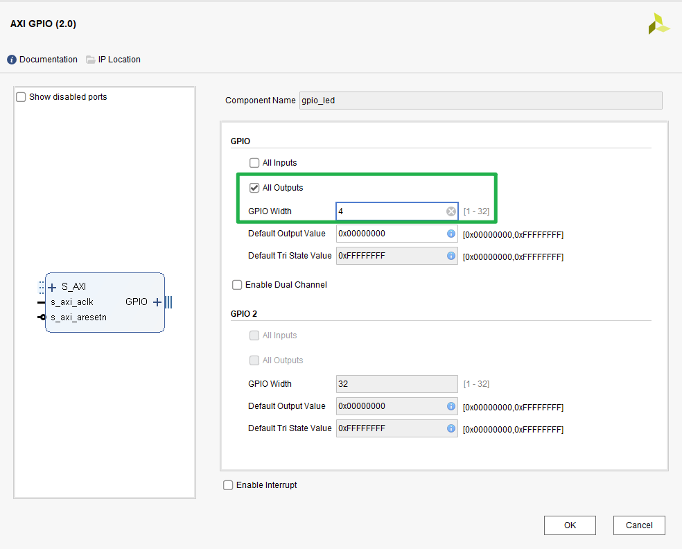
2.5 Add AXI_GPIO
Add AXI_GPIO IP.
I have 4 user LEDs on the board, so I selected GPIO Width=4, and All Outputs.
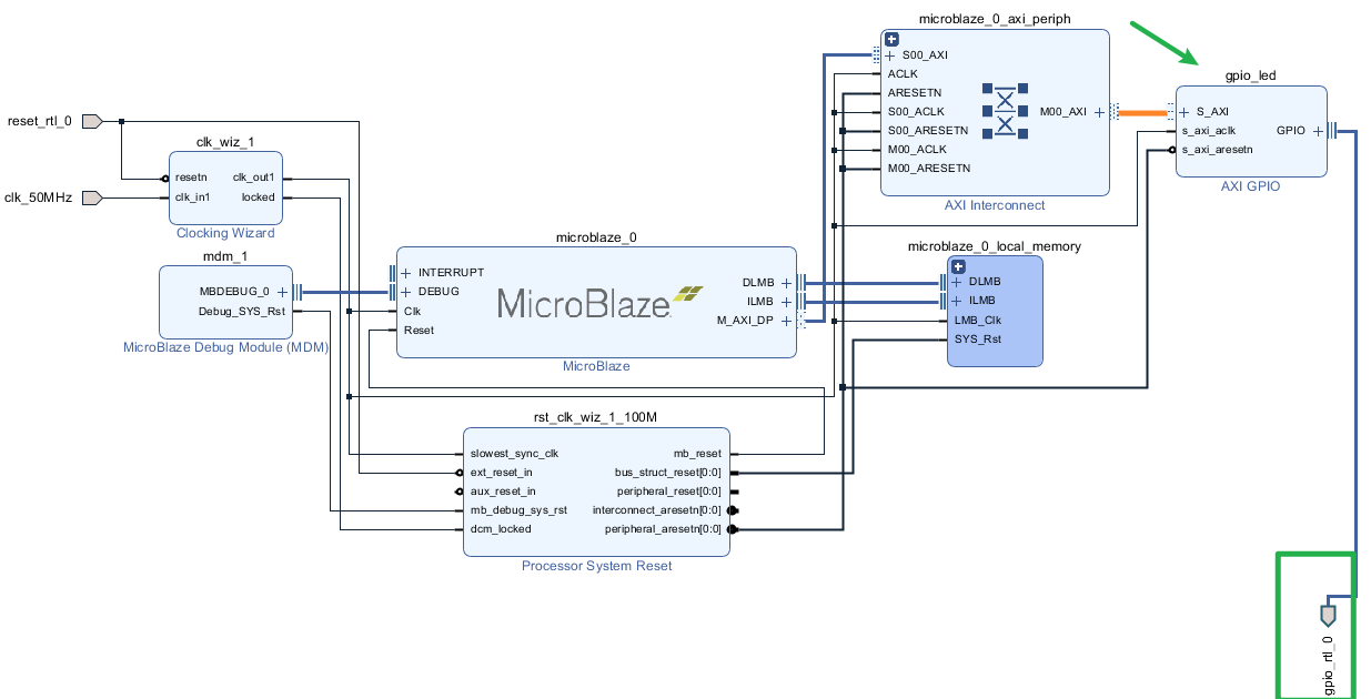
Run Connection Automation again, GPIO IP is automaticly connected to the Microblaze system, meanwhile, an output port was added to the block dragram.
2.6 Validate Design
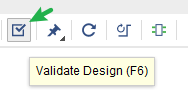 Successful.
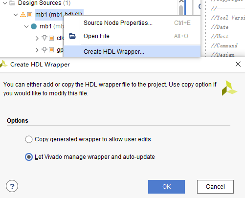
2.7 Create wrapper (top level design)
Automaticaly generate a top level design for the project.
 The final structure:
 top-mb1-all the IPs
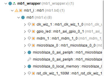
The generated wrapper:
| |
2.8 Define Contraints
- Run Synthesis
- From the top menus,
layout-I/O planning - Assign correct
package pinsandI/O standardfor reset button, (read the schematics or documentations of your board) - Save the constraint
.xdcfile.
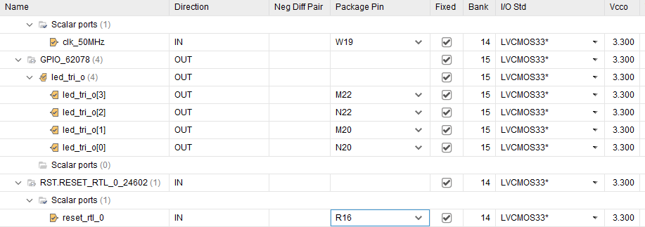
generated .xdc file :
set_property PACKAGE_PIN W19 [get_ports clk_50MHz]
set_property IOSTANDARD LVCMOS33 [get_ports clk_50MHz]
set_property PACKAGE_PIN N20 [get_ports {led_tri_o[0]}]
set_property PACKAGE_PIN M20 [get_ports {led_tri_o[1]}]
set_property PACKAGE_PIN N22 [get_ports {led_tri_o[2]}]
set_property PACKAGE_PIN M22 [get_ports {led_tri_o[3]}]
set_property IOSTANDARD LVCMOS33 [get_ports {led_tri_o[3]}]
set_property IOSTANDARD LVCMOS33 [get_ports {led_tri_o[2]}]
set_property IOSTANDARD LVCMOS33 [get_ports {led_tri_o[1]}]
set_property IOSTANDARD LVCMOS33 [get_ports {led_tri_o[0]}]
set_property IOSTANDARD LVCMOS33 [get_ports reset_rtl_0]
set_property PACKAGE_PIN R16 [get_ports reset_rtl_0]
2.9 Bitstream Generation
All default settings:
- Implementation
- Generate bitstream
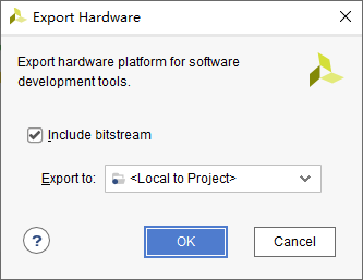
2.10 Export Hardware
File-export-export Hardware with default settings.
2.11 Open SDK
File-Launch SDK
3 In SDK
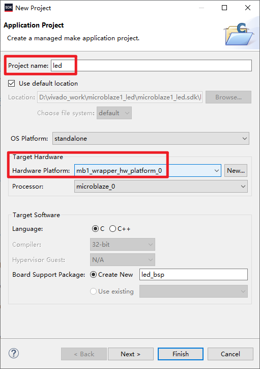
3.1 New Application Project
- In SDK, New-Application Project
- Finish, create an empty project
3.2 Add Sample Code
Add main.c at src directory.
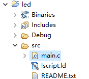
main.c:
| |
- For initialization of GPIO, refer to
xgpio_example.c: gpio: xgpio_example.c File Reference - For device id, look for
GPIO_LED(the name ofAXI_GPIOip from Vivado Block Design) inxparameters.h:
| |
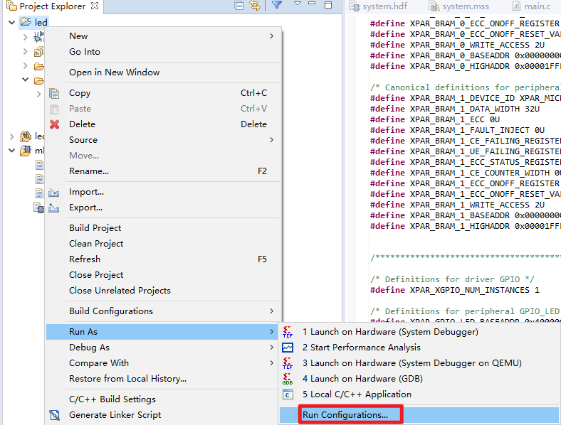
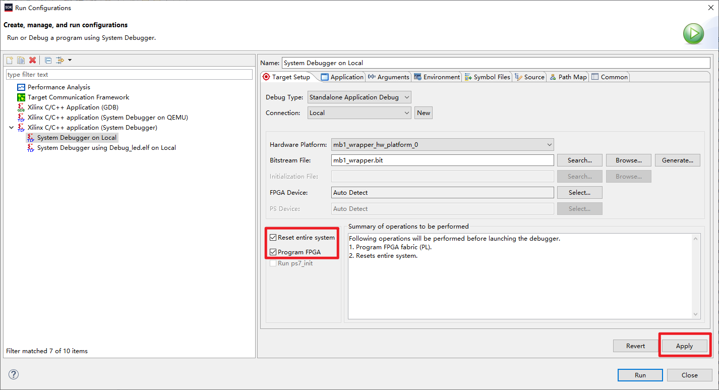
3.3 Debug
3.3.1 Run Configuration
3.3.2 Build Project
Project-Build All
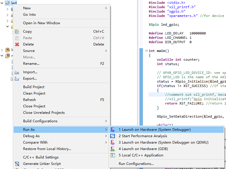
3.3.3 Program FPGA
Right click Project led-Run as-Launch on Hardware.
After a few seconds, the LEDs should be blinking.
Basically, the SDK is just like other IDEs for ARM or TI DSP, though I haven’t used these in a while, either.
4 Links
Maybe I should have used a newer Vivado version:
Starting in the 2019.2 release, the Xilinx SDK development environment is unified into an all-in-one Vitis™ unified software platform.
- Most of the steps are from this video: Digilent Nexys: Microblaze and GPIO Design Implementation - YouTube
- Another toturial: MicroBlaze Quickstart Video
- volatile int: declaration - Why is volatile needed in C? - Stack Overflow
volatiletells the compiler not to optimize anything that has to do with thevolatilevariable.
- MicroBlaze - section .text will not fit in region (xilinx.com)
- Step By Step Guide To Xilinx SDK Project Migration To Vitis
- gpio: xgpio_example.c File Reference
- search for
xgpio_example.cinside the Vivado installation directory.
- search for